esp8266开发板设计:D1 mini Plus V1.0
D1 mini Plus
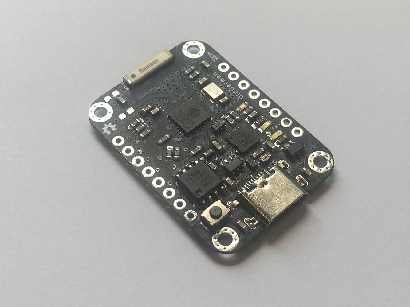
A development kit Improved from D1 mini Pro V1.0.0
The first test board welded by hand and it works great!
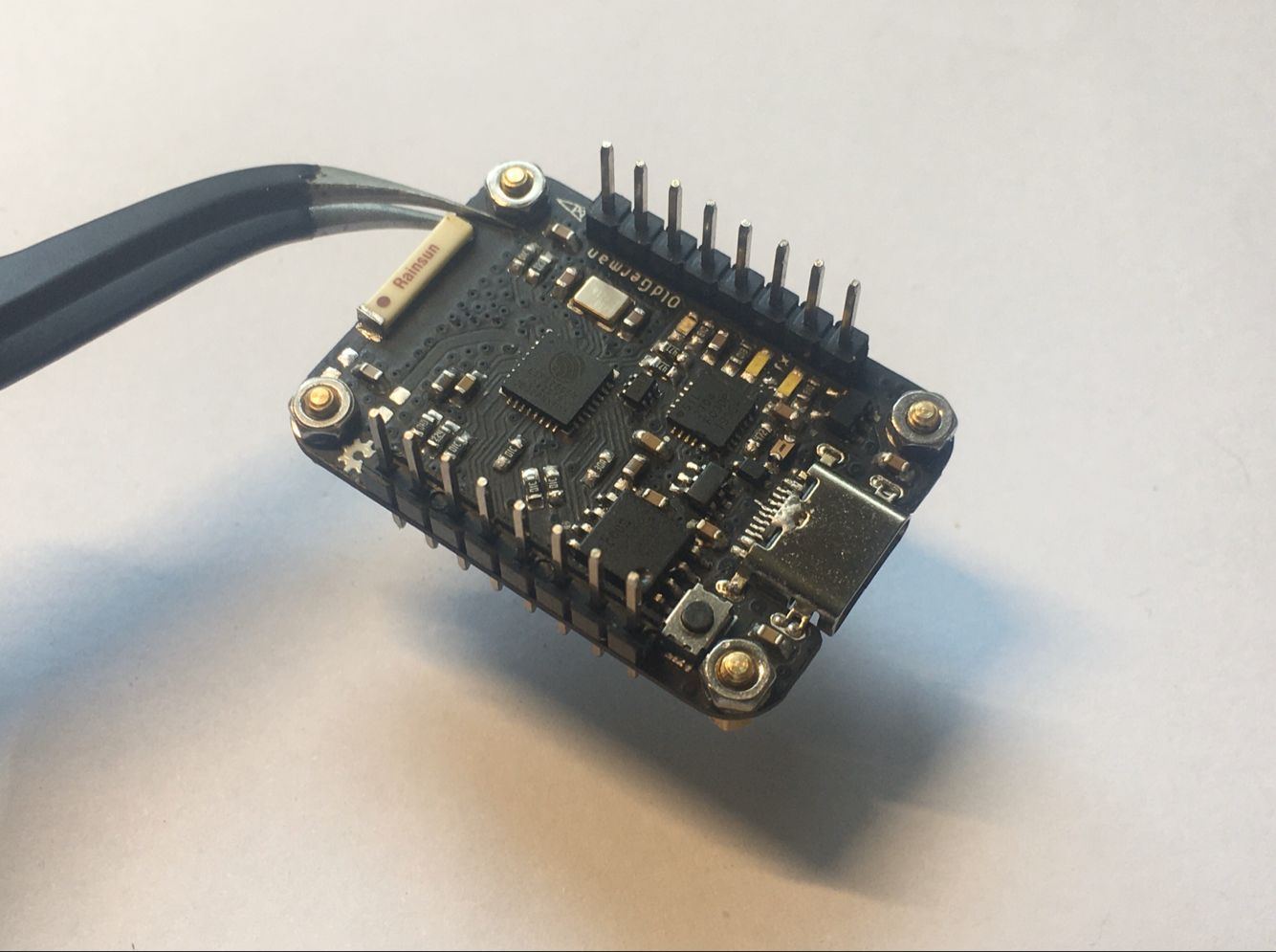
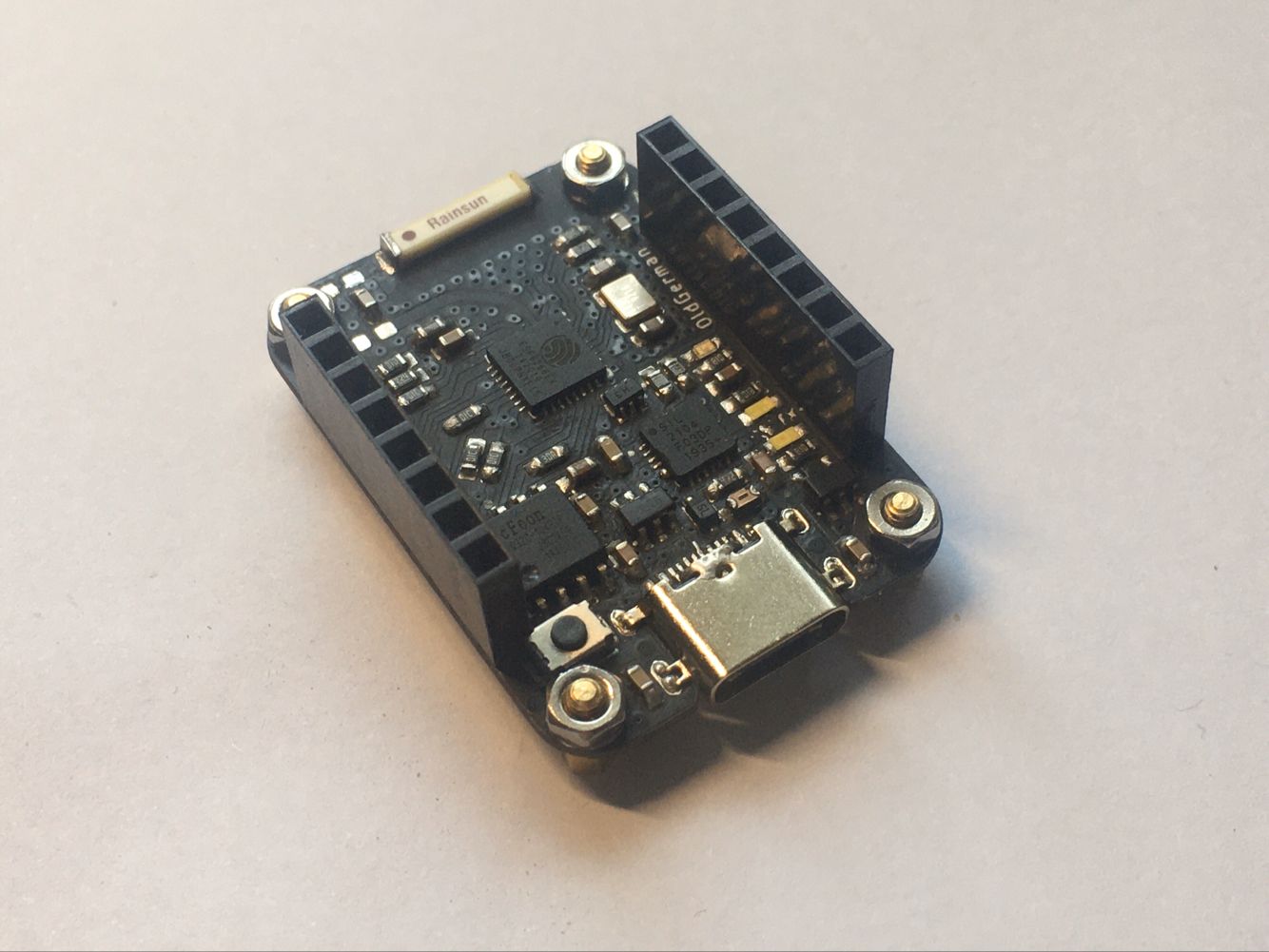
Add connector & bolts for fixing
 |
 |
|
Features
- Pin to pin with D1 mini development kits
- Double-sided PCB layout, the board thickness is 0.8mm, size is 36.0mm x25.6mm
- All components are on one side
- Discrete components are packaged in 0603, which is easy to solder by hand
- There are four M2 holes around the PCB that are easy to fix
- USB C Connector horizontal In-Board 1.6mm supports positive and negative insertion
- Leads the TX & RX LEDs GPIO.0-1 of cp2104, you can use AN721 to turn them on or off
- Use the USBLC6-2 ic to ESD protection, If you don't need it, you don't need to solder, this will not affect the serial port work
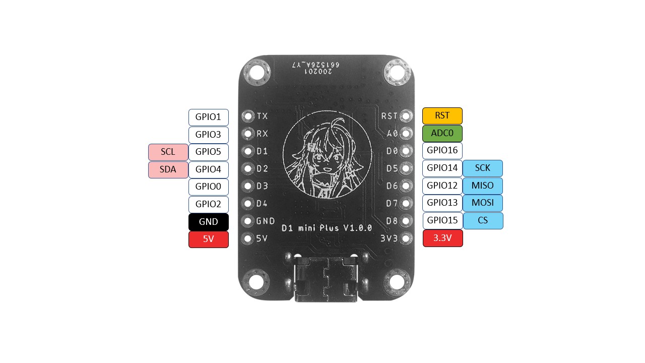
Pin Map (Back View)
There is no cartoon logo on the back of the shared PCB file XD
Designator & Parameter
| Qty | Value | Device | Package | Parts | Description |
|---|---|---|---|---|---|
| 1 | 26MHz | 3225_CRYSTALL | 3.2X2.5_KX-7 | U$3 | EPSON TSX-3225 ±10ppm 9pf |
| 2 | 2.54mm | CONN_08NO_SILK_FEMALE_PTH | 1X08_NO_SILK | J1, J2 | 0.1 inch spaced/style header connections |
| 1 | U1 | ME6211C33M5G-N | SOT23-5 | U$1 | 3.3V 500mA 低差压线性稳压器 |
| 1 | 2.4GHz | RAINSUN_AT9520 | AN9520 | U$4 | Ceramic antenna 陶瓷天线 |
| 1 | USB-C_BELOW_BOARD | USB-C_BLOW_BOARD | USB-C | ||
| 2 | blank | RESISTOR0603 | 603 | R11, R12 | Generic Resistor Package |
| 1 | 100k | RESISTOR0603 | 603 | R13 | Generic Resistor Package |
| 5 | 100nF | CAP-0603 | 603 | C4, C7, C12, C13, C14 | |
| 5 | 10k | RESISTOR0603 | 603 | R7, R8, R15, R16, R17 | Generic Resistor Package |
| 2 | 10pF | CAP-0603 | 603 | C5, C11 | |
| 1 | 10uF | CAP-0603 | 603 | C9 | |
| 1 | 12k | RESISTOR0603 | 603 | R5 | Generic Resistor Package |
| 3 | 1k | RESISTOR0603 | 603 | R4, R9, R10 | Generic Resistor Package |
| 1 | 1uF | CAP-0603 | 603 | C8 | |
| 2 | 1uF/X7R | CAP-0603 | 603 | C1, C2 | |
| 1 | 200 | RESISTOR0603 | 603 | R6 | Generic Resistor Package |
| 1 | 220k | RESISTOR0603 | 603 | R14 | Generic Resistor Package |
| 2 | 4.7uF | CAP-0603 | 603 | C3, C6 | |
| 2 | 470 | RESISTOR0603 | 603 | R2, R3 | Generic Resistor Package |
| 1 | 4k7 | RESISTOR0603 | 603 | R1 | Generic Resistor Package |
| 1 | 5.6pF | CAP-0603 | 603 | C10 | |
| 1 | 6V 0.5A | RESISTOR0603 | 603 | F1 | Generic Resistor Package |
| 1 | B5819W | DIODE-SOD323-R | SOD323-R | D3 | Schottky DIODE |
| 3 | BLUE | LED-BLUE0603 | LED-0603 | D1, D2, D4 | Blue SMD LED |
| 1 | CP2104 | CP2104 | QFN24_4MM_SMSC | U3 | CP2104 - USB to UART Bridge |
| 1 | ESP8266 | ESP8266 | QFN32-5X5MM | U1 | Espressif ESP8266 WiFi/Microcontroller SoC |
| 1 | SWITCH | MOMENTARY-SWITCH-SPST-SMD | TACTILE_SWITCH_SMD | S1 | Momentary Switch (Pushbutton) - SPST |
| 1 | U2 | UMH3N | SOT363 | U$2 | NPN 100mA 50V Complex Digital Transistors (Bias Resistor Built-in Transistors) |
| 1 | USBLC6-2 | USBLC6-2SOT23-6 | SOT23-6 | U$11 | low capacitance ESD protection |
| 1 | W25Q32FV | W25Q32FVSS | SOIC-8 | U2 | W25Q32FV 32Mb (4MB) Serial Flash Memory |
SPI test: ST7789V Graphicstest
Testing in SPI FREQUENCY 40000000
I2C test: read MPU6050 DMP Euler angles in degrees
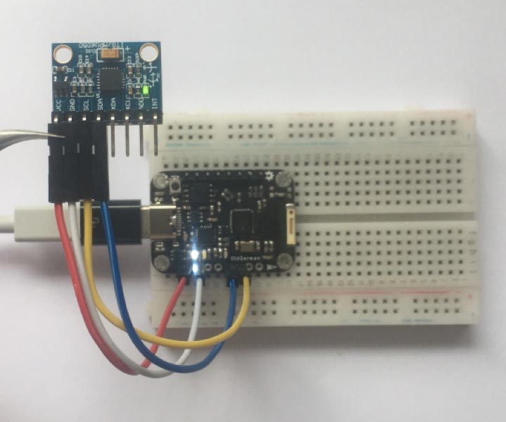 |
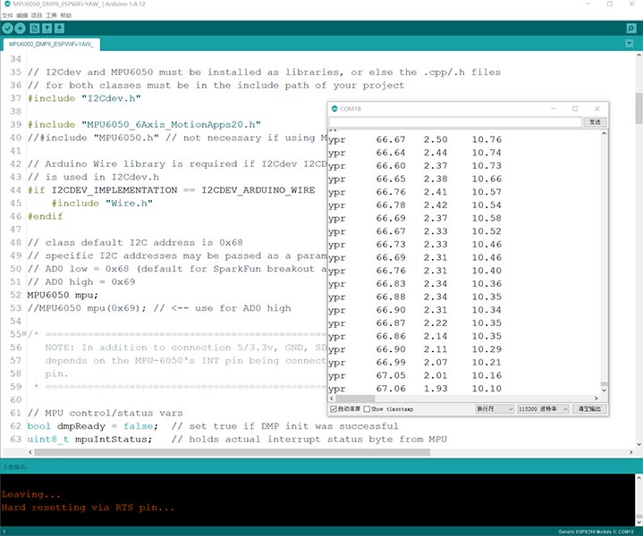
|
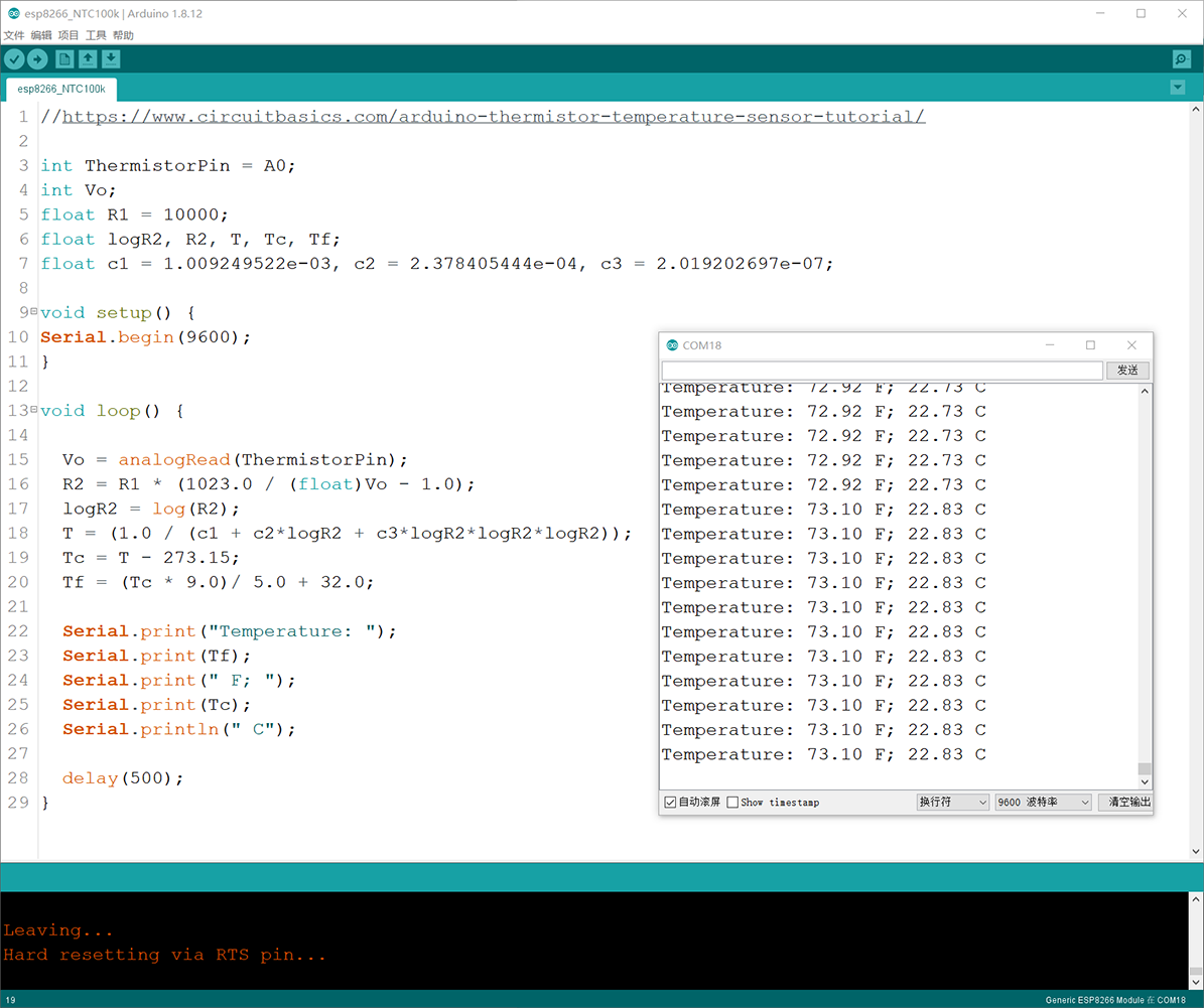
ADC0 test: basic NTC thermistor measurement circuit
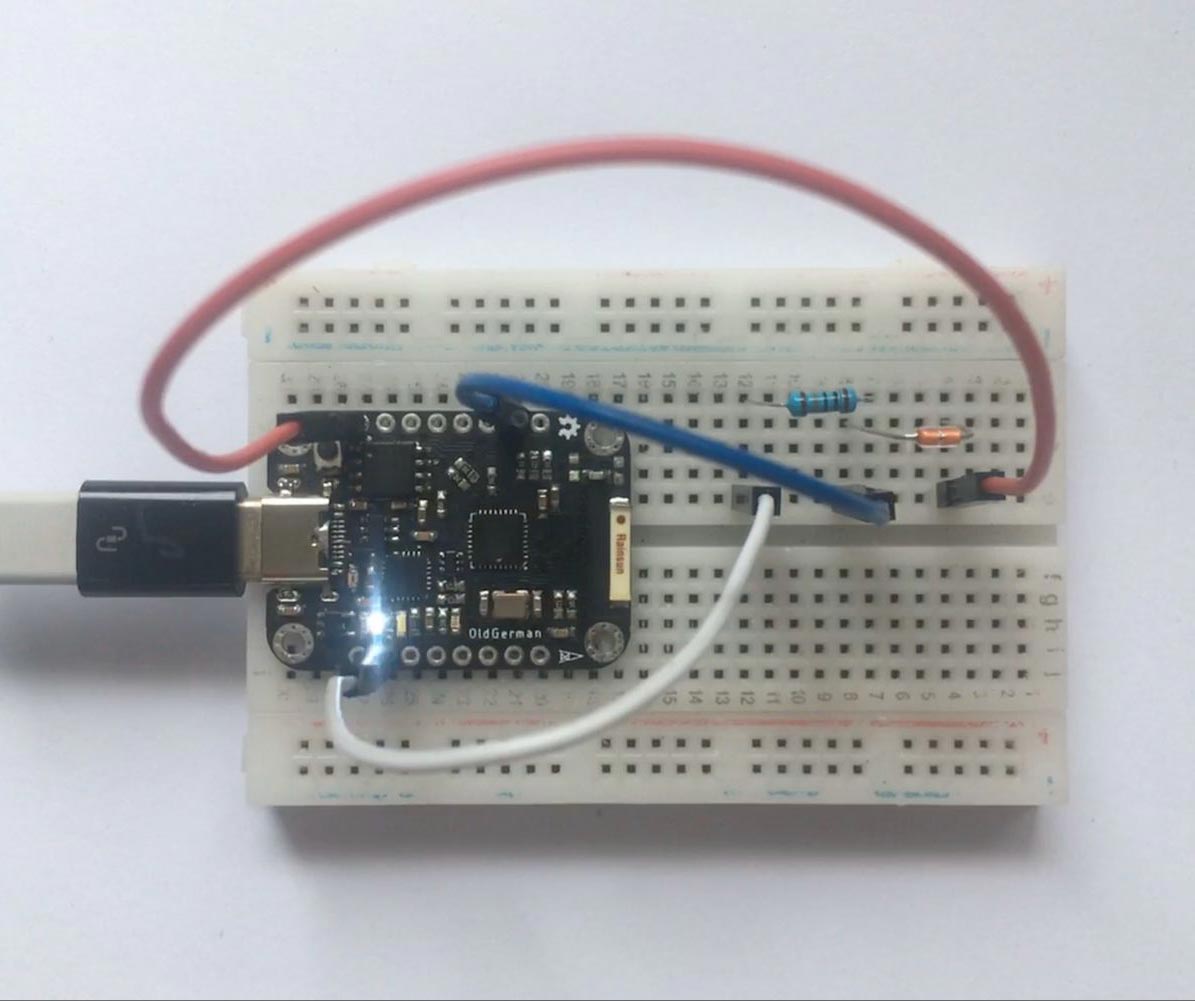 |
|
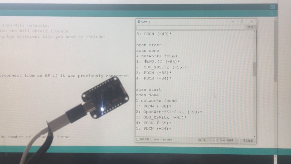
Wifi scan test
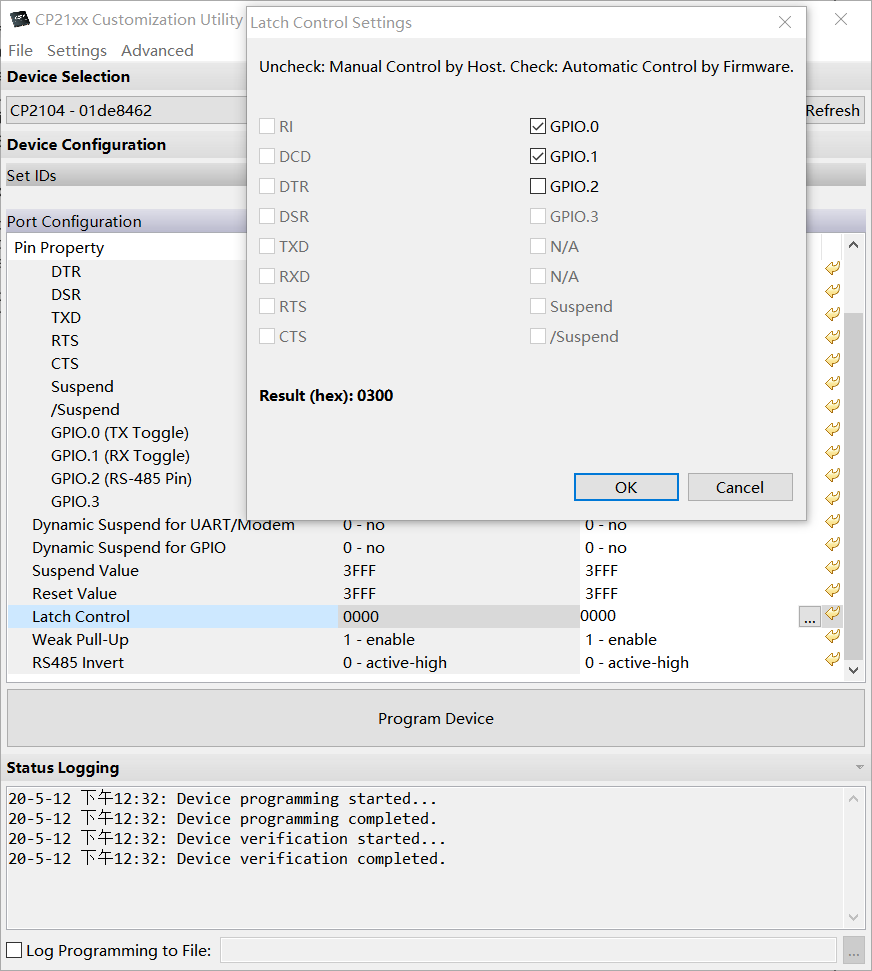
CP2104 TX & RX LEDs - How to get them working?
First, download and unzip the AN721: Download link, for windows, click in this document
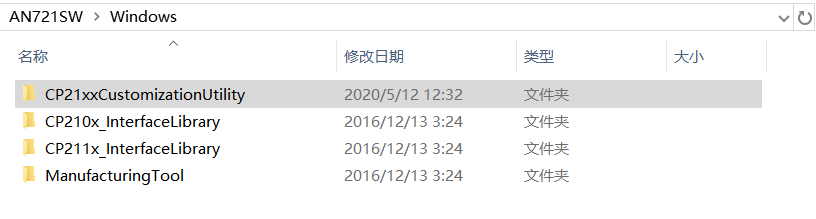
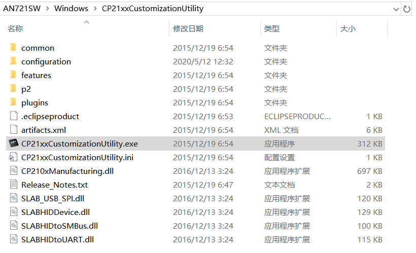
Second, run the CP21xxCustomizationUtility.exe
Third, according to the page 28 from AN721: USBXpress™ Device Configuration and Programming Guide, we set the latch for ticking the GPIO0 and GPIO1;
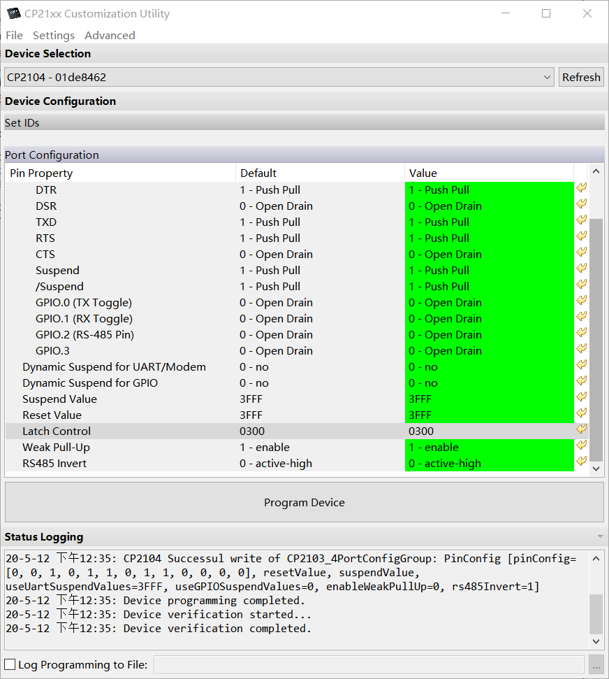
Click "Program Device" button and wait a minute,the change will be saved in CP2104:
 |
|
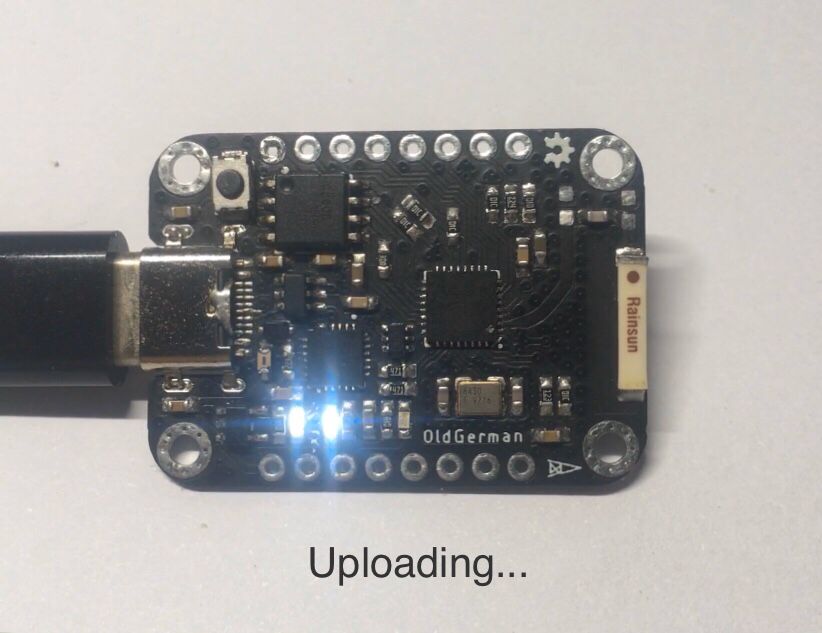
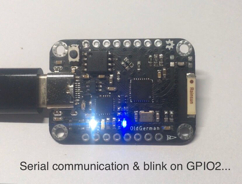
Finally, whether you upload a program or use a serial port, the led of CP2104 will flash, enjoy it 😂
 |
|
- 本文链接: http://oldgerman.github.io/db8555d9/
- 版权声明: 本博客所有文章除特别声明外,均采用 BY-NC-SA 许可协议。转载请注明出处!